")
")
Delta Mega SmartDrive – Complete Installation Guide
This tutorial is designed to guide you step by step through the installation of the Delta Mega SmartDrive on your Sega Mega Drive / Genesis. This solution transforms your console into a multi-region, allows PAL / USA / JAP, 50Hz / 60Hz, OSD, as well as convenient control via the controller ou le Reset button.
MD1: intermediate. MD2: advanced, micro-soldering.
The console must be powered off before any work is carried out.
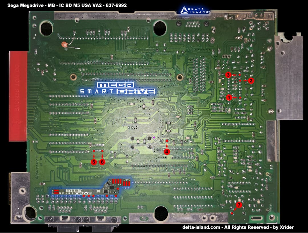
Accurately identify the motherboard revision before installation.

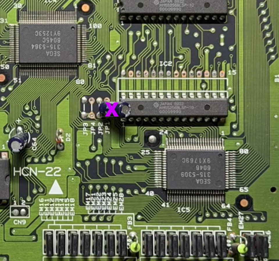
Red = PAL • Blue = USA • Purple = JAP
Instant console reboot.
🚀 Mega SmartDrive – Modernize your Mega Drive
Discover the Mega SmartDrive, the ultimate accessory to transform your Sega Mega Drive / Genesis into a smart and modern system while preserving its authenticity.
Thanks to its advanced features and optimized installation, the Mega SmartDrive redefines the gaming experience by offering flexibility, compatibility, and ease of use.
Your console becomes fully region-free, with no external switches or complex modifications.
A modern solution that simplifies use and adds real everyday convenience.
Red = PAL • Blue = USA • Purple = JAP
An aesthetic and practical option for modding enthusiasts.
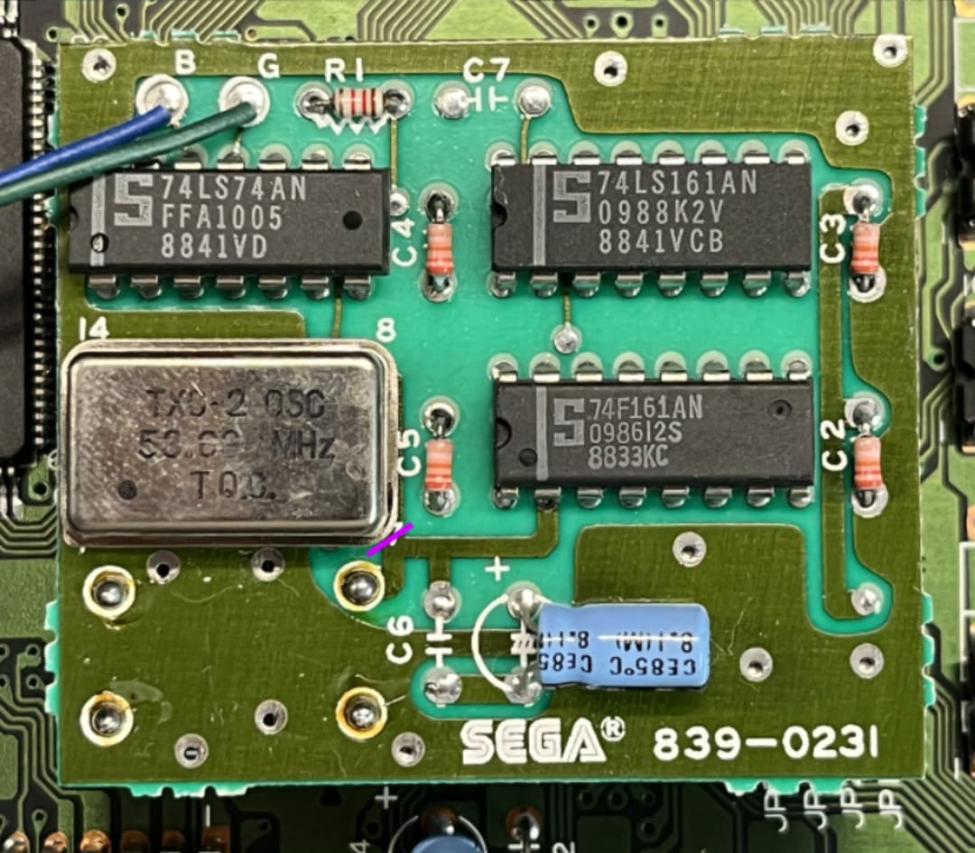
- PAL : 53.203424 MHz
- NTSC : 53.693175 MHz
For optimal quality, using an RGB SCART cable is strongly recommended.
Ideal for users of EverDrive ou les sessions intensives.
Fast, clean, and reliable installation, even for intermediate users.
✔ Discreet installation
✔ Intuitive interface
✔ Maximum compatibility
✔ Modernized experience
Join the era of retro intelligence with Mega SmartDrive — where authenticity meets innovation.
• Work on a clean, stable, and well-lit surface.
• Use a suitable soldering iron, flux, and a fine tip.
• Always inspect your traces and solder joints with magnification before reassembly.
✨ Why Delta Mega SmartDrive?
- PAL / USA / JAP selection
- 50Hz / 60Hz frequencies
- Console made region-free
- Changement via controller 1
- Selection possible via Reset
- On-screen OSD + last mode memory
- Optional bi-color LED
- Instant visual feedback
- Cleaner approach than a classic switchless mod
🧰 Required tools
- Delta Mega SmartDrive
- Screwdriver suitable for your console
- Fine-tip soldering iron
- Electronics solder
- Flux strongly recommended
- Scalpel precision
- Magnifier / microscope recommended
- For MD2: thin Kynar 30AWG wire
🌍 Supported revisions
Support for all motherboard revisions :
VA0, VA1, VA3, VA4, VA5, VA6 et VA7
✔ Compatibility with all regions : PAL / USA / JAP
Special case: la MD1 VA7 requires the "Delta SmartDrive MD2"
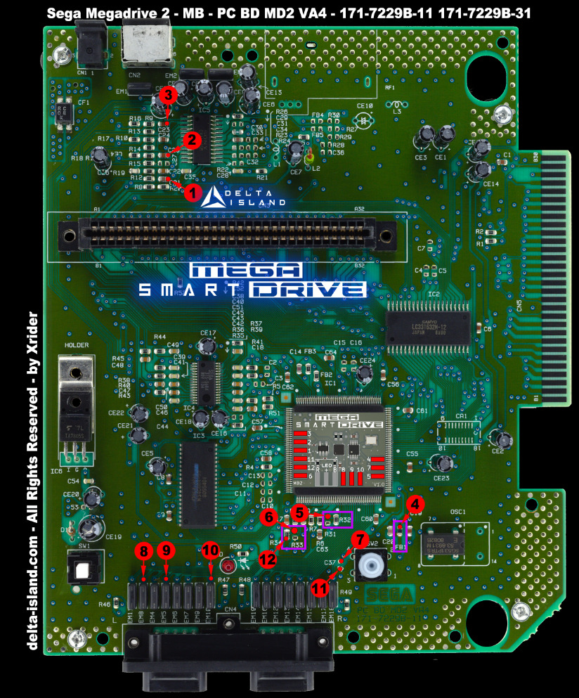
Mega Drive / Genesis 2 :
VA0, VA1, VA2, VA3 et VA4
✔ Compatibility with all regions : PAL / USA / JAP
🔧 1 - Disassembling the console
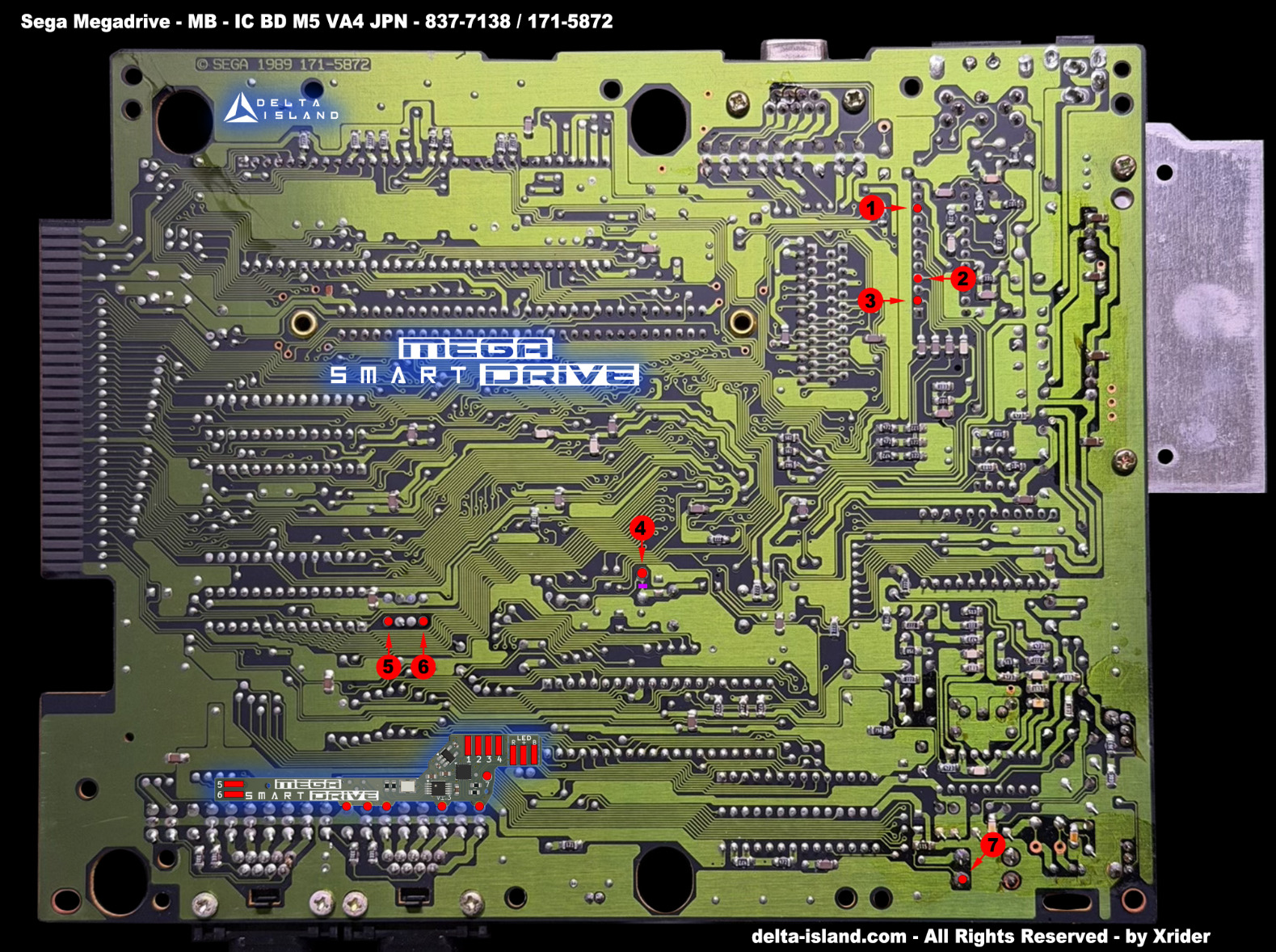
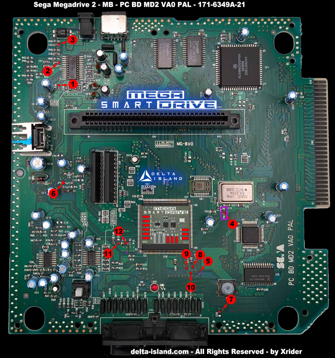
🧭 2 - Identifying your Sega Mega Drive / Genesis motherboard
Before any installation, it is essential to accurately identify your motherboard revision. Each version requires a specific installation diagram.
🎮 Mega Drive / Genesis 1 (MD1)


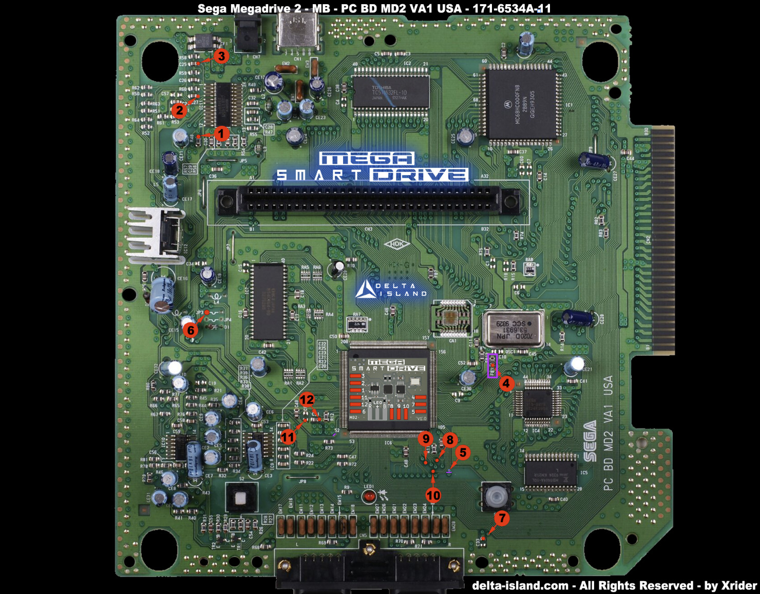
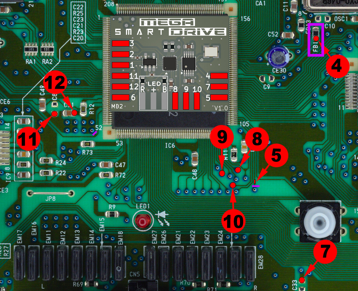
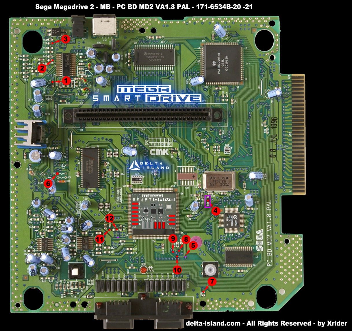
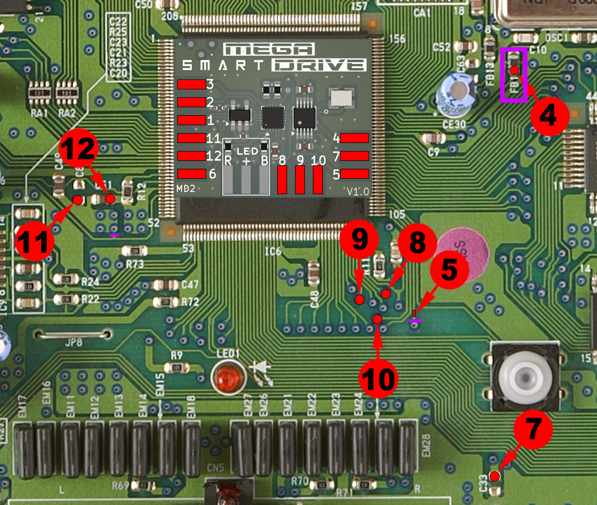
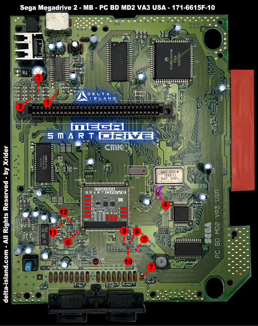
🎮 Mega Drive / Genesis 2 (MD2)


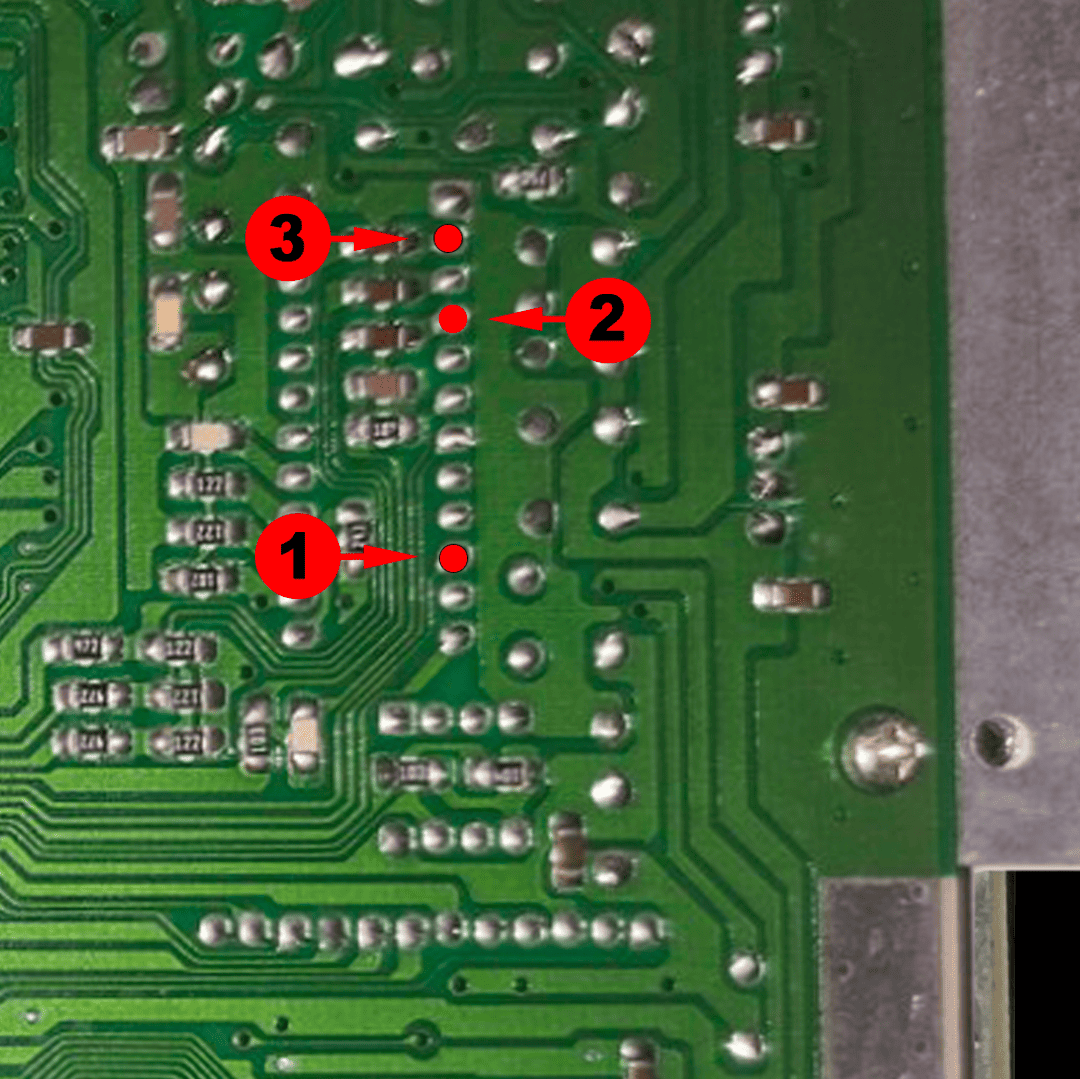
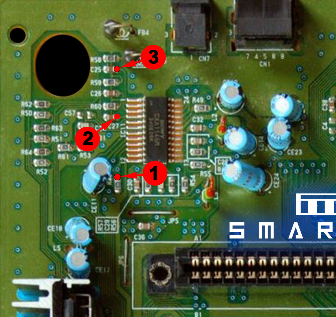
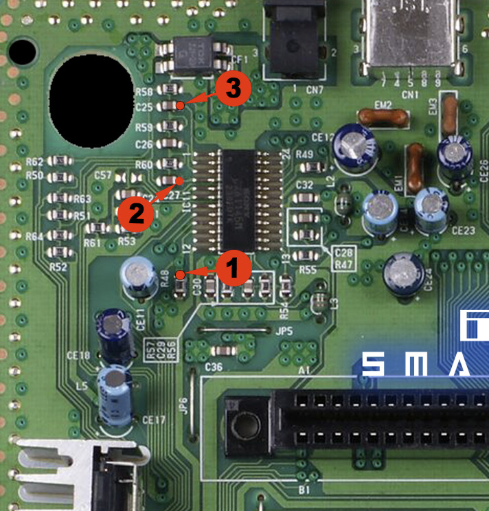
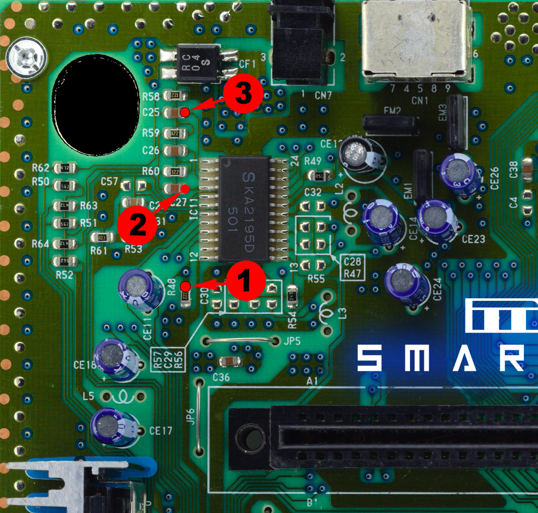
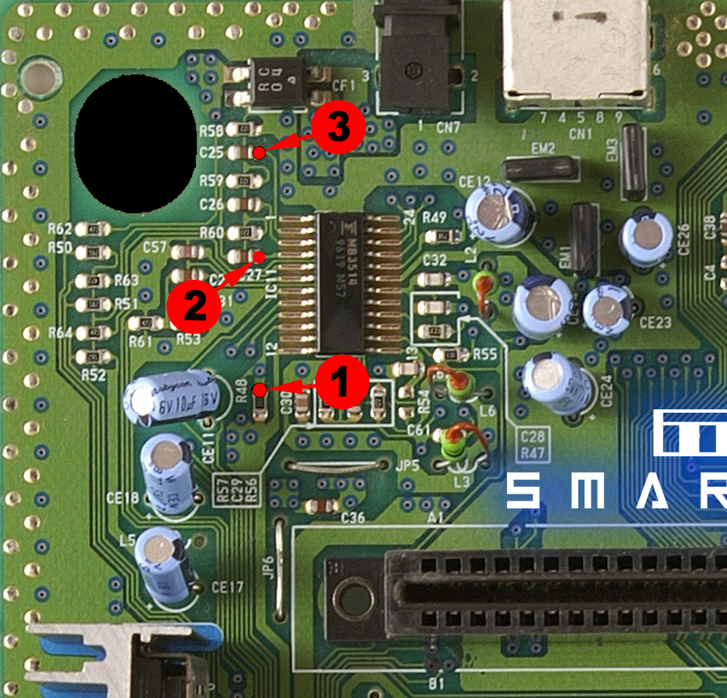
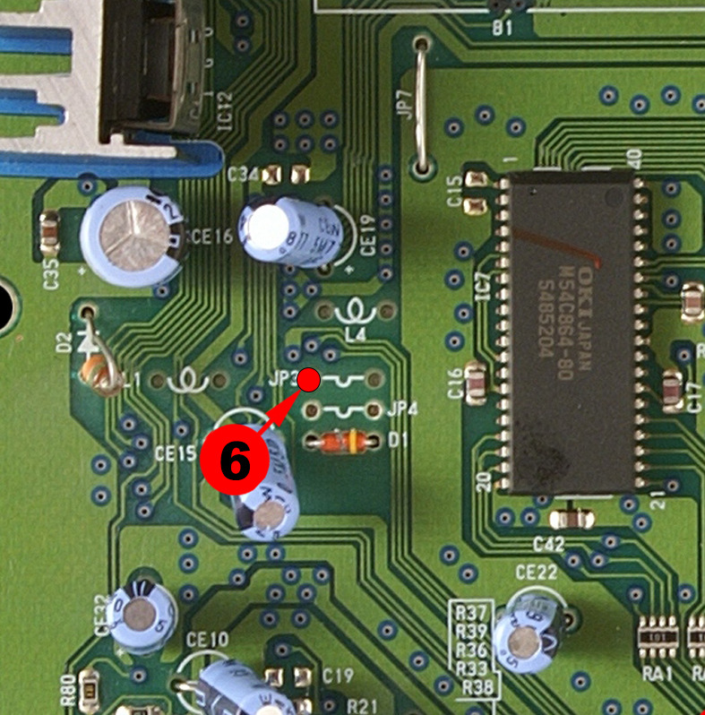
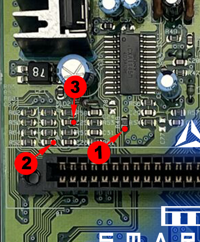
🧩 3 - Complete installation diagrams by motherboard
If your motherboard revision does not appear in the list, please contact us via le forum Delta. We can then provide you with the specific installation diagram and add it to the tutorial.
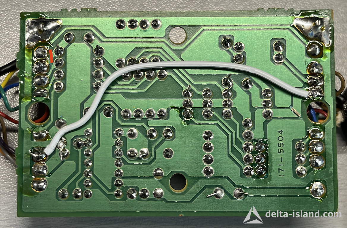
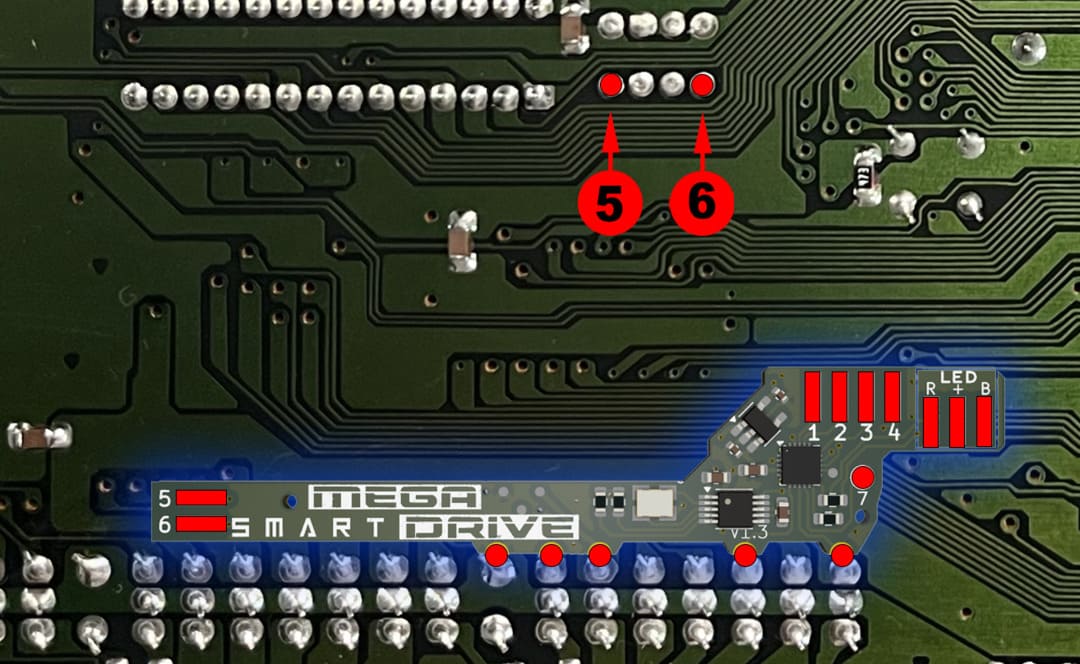
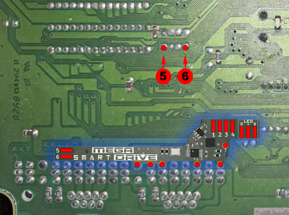
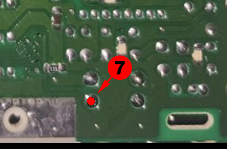
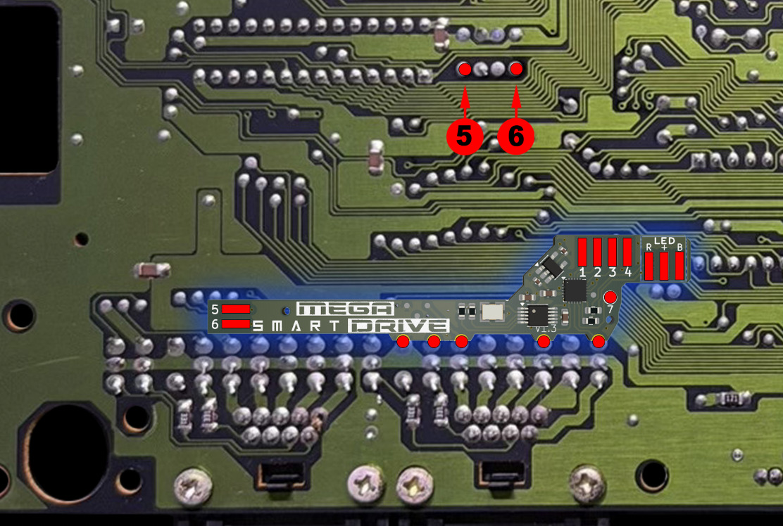
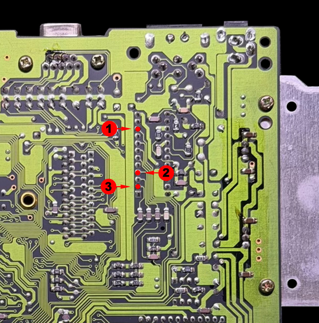
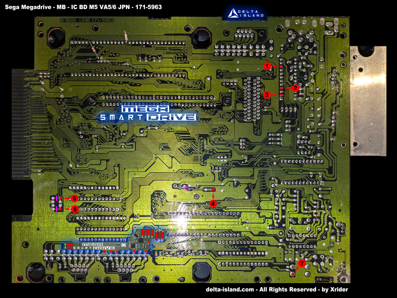
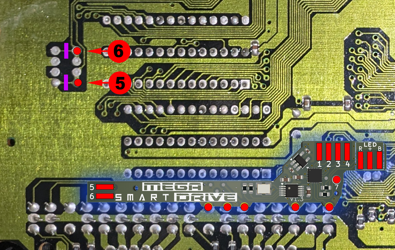
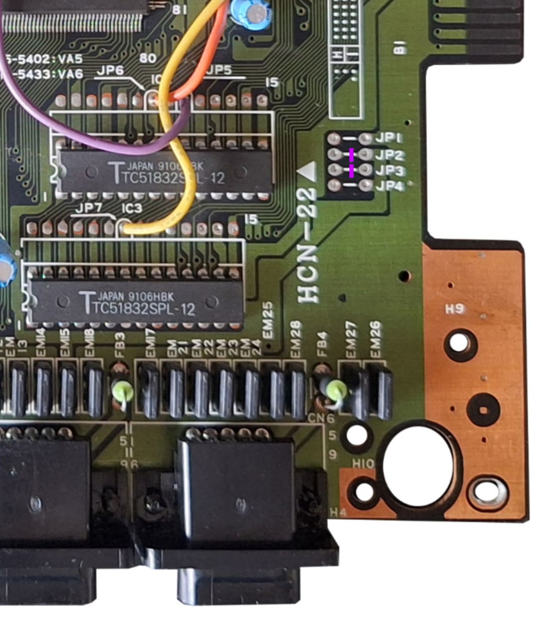
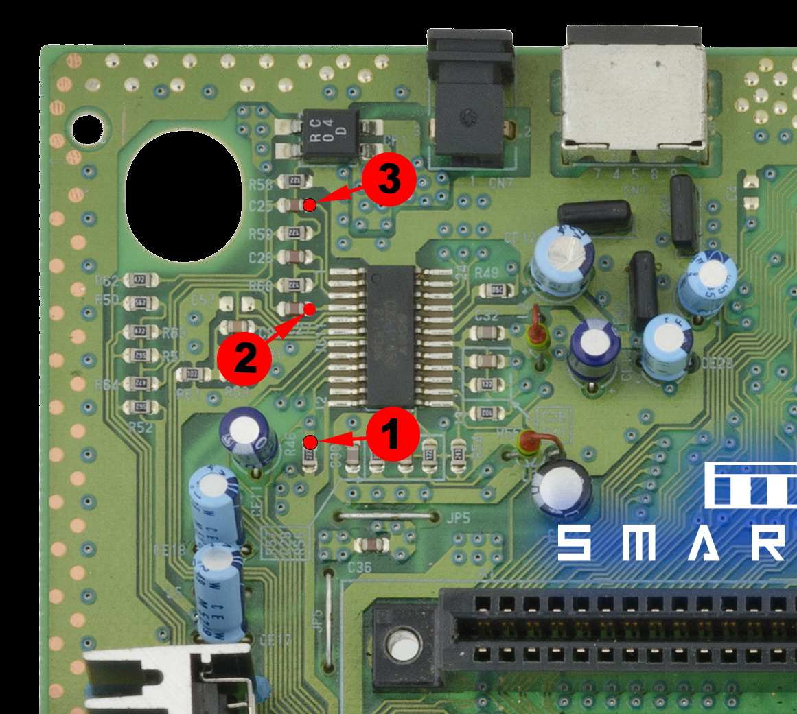
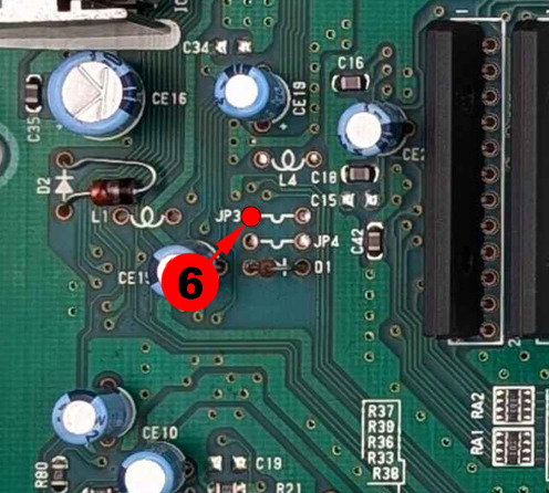
• Then position the Delta SmartDrive and make the solder joints according to the installation diagrams below.


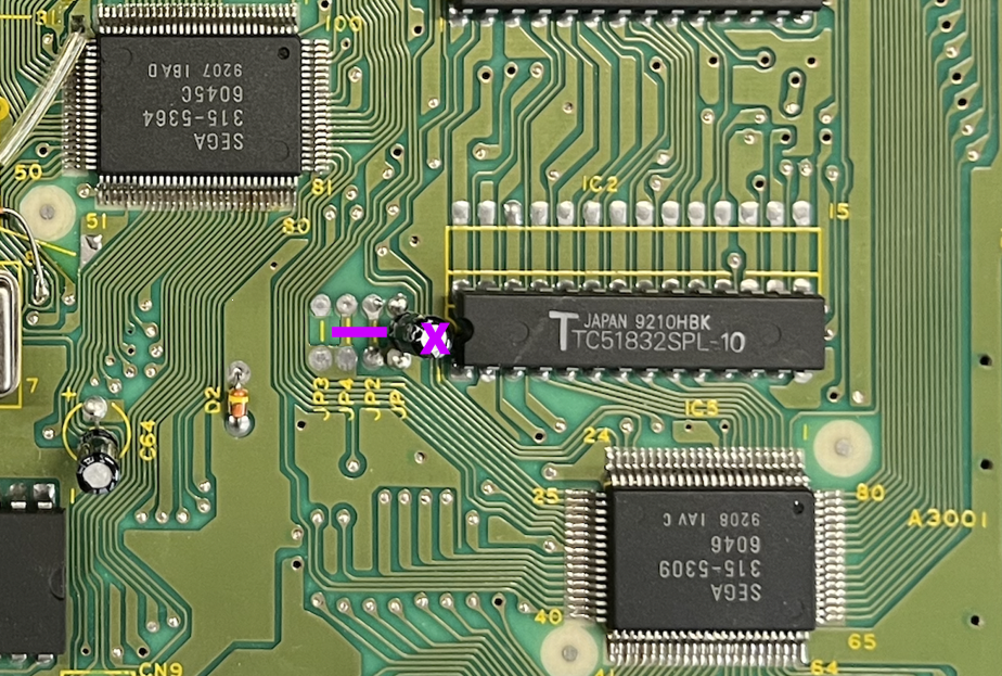
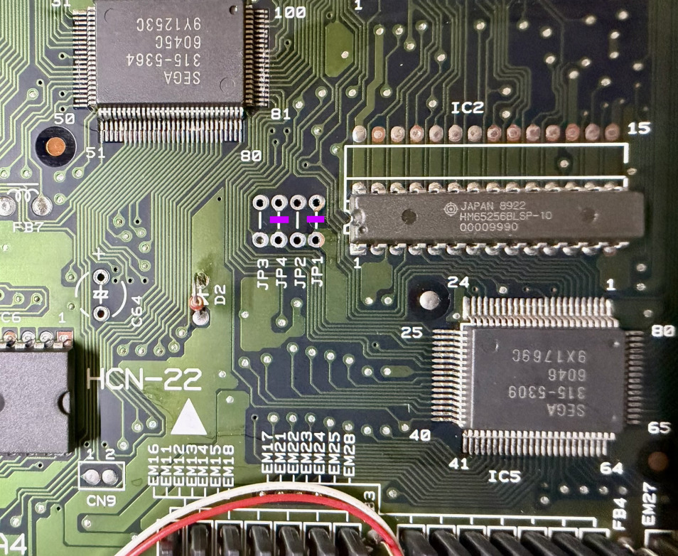
• If a capacitor is present on JP1 / JP2 / JP3 / JP4, remove it cleanly.
• Then position the Delta SmartDrive and make the solder joints according to the installation diagrams below.
• If a capacitor is present on JP1 / JP2 / JP3 / JP4, remove it cleanly.
• Then position the Delta SmartDrive and make the solder joints according to the installation diagrams below.
• If a capacitor is present on JP1 / JP2 / JP3 / JP4, remove it cleanly.
• Then position the Delta SmartDrive and make the solder joints according to the installation diagrams below.


• If a capacitor is present on JP1 / JP2 / JP3 / JP4, remove it cleanly.
• Then position the Delta SmartDrive and make the solder joints according to the installation diagrams below.
• If a capacitor is present on JP1 / JP2 / JP3 / JP4, remove it cleanly.
• Then position the Delta SmartDrive and make the solder joints according to the installation diagrams below.


• If a capacitor is present on JP1 / JP2 / JP3 / JP4, remove it cleanly.
• Then position the Delta SmartDrive and make the solder joints according to the installation diagrams below.


• Then position the Delta SmartDrive and make the solder joints according to the installation diagrams below.
The Mega Drive 1 VA7 version requires an MD2 SmartDrive PCB.
Fixez le SmartDrive MD2 avec un quality double-sided adhesive before wiring.


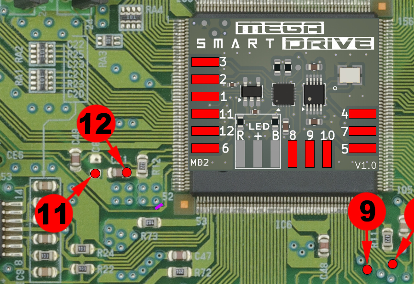
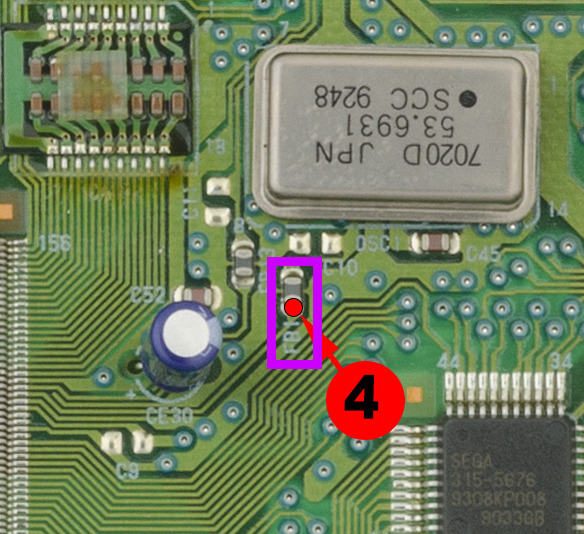
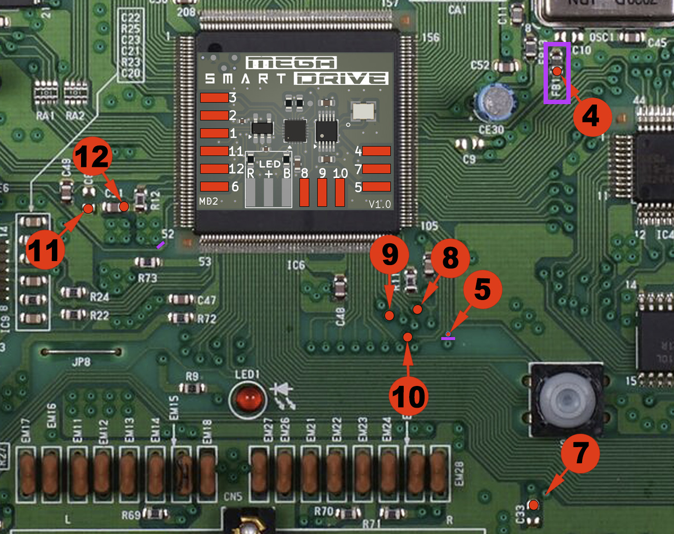
Advanced micro-soldering:
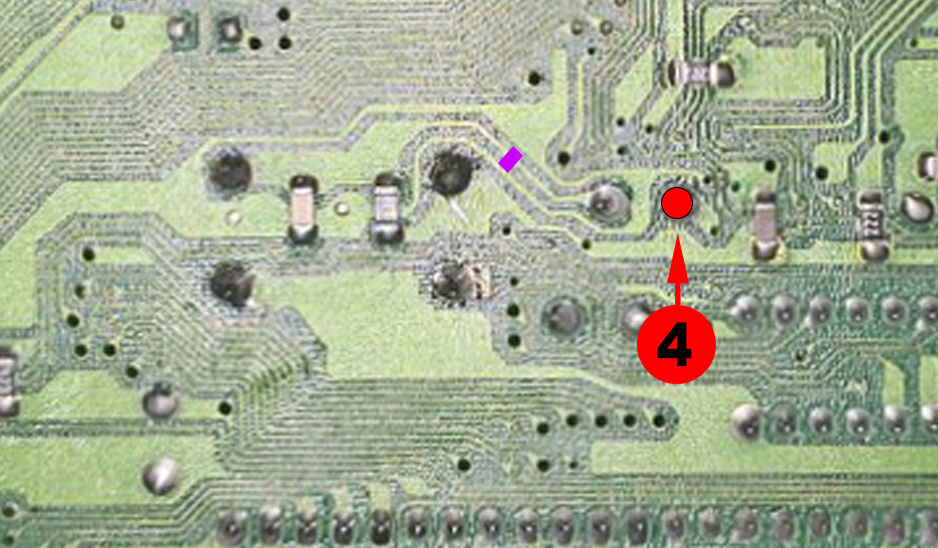
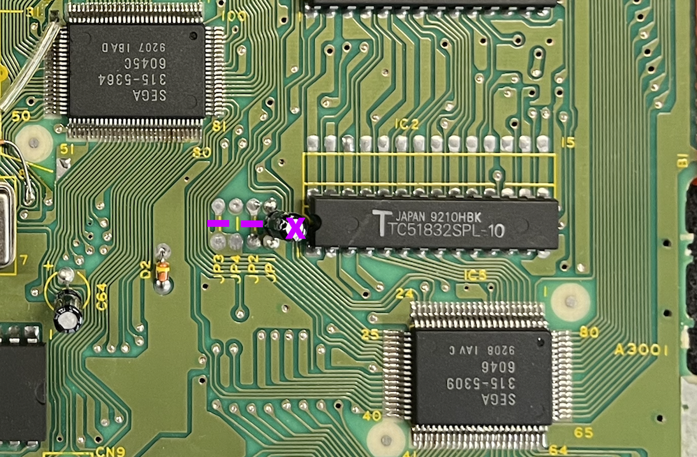
• Carefully cut the 2 traces marked in purple.
• If a jumper is present on JP3 or JP4, remove it.
• Remove the SMD ferrite bead FB1 indicated on the diagram.
• Preferably use Kynar 30AWG and flux.
• Fix the SmartDrive MD2 with quality double-sided adhesive before wiring.
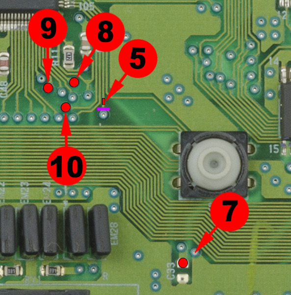
Recommended method:
To avoid stress on a fragile point:
1. First solder the wire to the SmartDrive board.
2. Then solder the other end to the previously tinned trace.
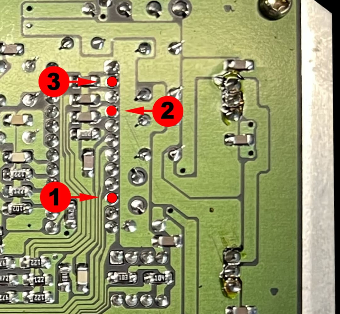
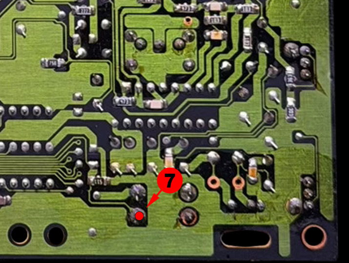
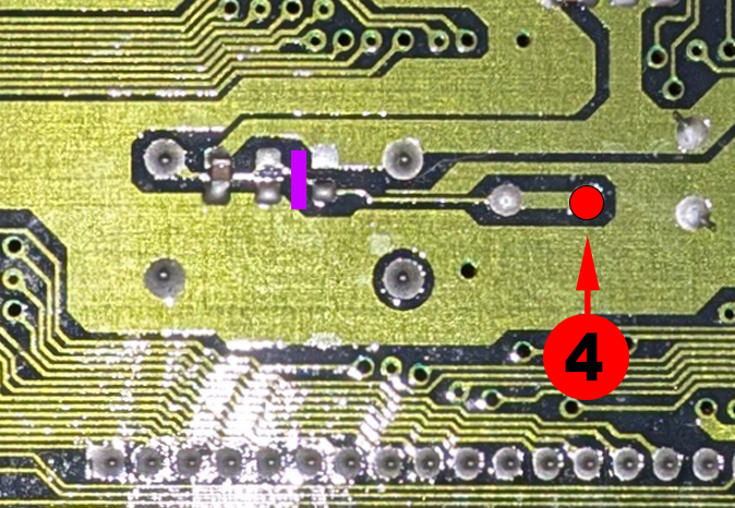
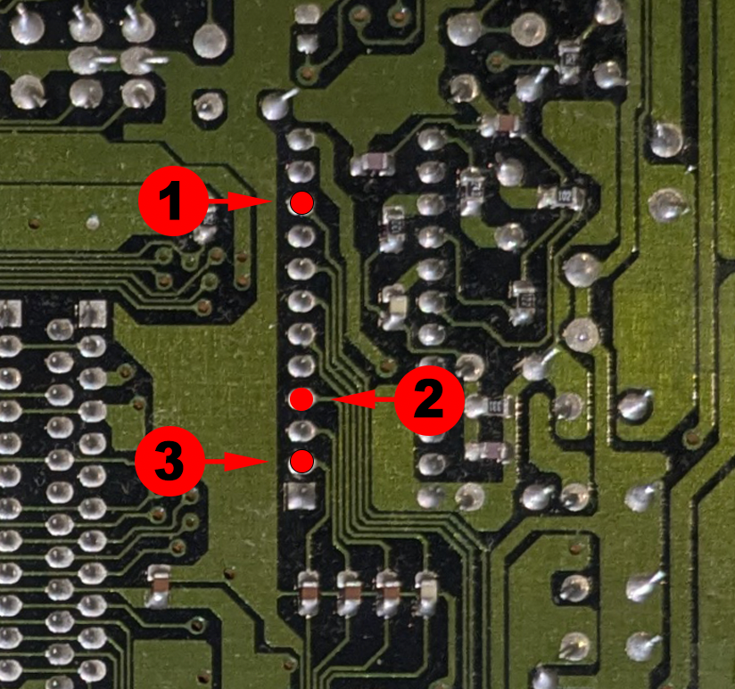
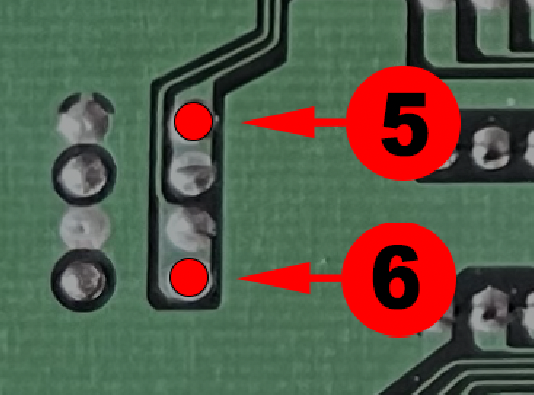
These points require lightly scraping away the protective lacquer to expose the copper.
- Then tin the solder point with a small amount of solder.
- Using flux is strongly recommended to obtain a clean and reliable solder joint.
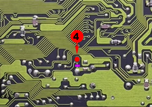
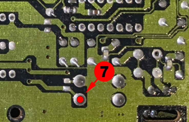
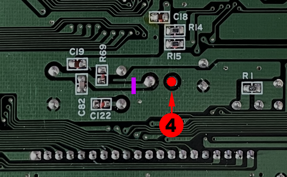
This point requires lightly scraping away the protective lacquer to expose the copper trace.
- Then tin the trace with a small amount of solder.
- Using flux is strongly recommended to obtain a clean and reliable solder joint.

Advanced micro-soldering:
• Carefully cut the 2 traces marked in purple.
• If a jumper is present on JP3 or JP4, remove it.
• Remove the SMD ferrite bead FB1 if indicated on the diagram.
• Preferably use Kynar 30AWG and flux.
• Fix the SmartDrive MD2 with quality double-sided adhesive before wiring.
Recommended method:
To avoid stress on a fragile point:
1. First solder the wire to the SmartDrive board.
2. Then solder the other end to the previously tinned trace.
These points require lightly scraping away the protective lacquer to expose the copper.
- Then tin the solder point with a small amount of solder.
- Using flux is strongly recommended to obtain a clean and reliable solder joint.
This point requires lightly scraping away the protective lacquer to expose the copper trace.
- Then tin the trace with a small amount of solder.
- Using flux is strongly recommended to obtain a clean and reliable solder joint.


• Coupez soigneusement les 2 traces marked in purple.
• If a jumper is present on JP3 ou JP4, retirez-le.
• Preferably use Kynar 30AWG et du flux.
• Fixez le SmartDrive MD2 avec un quality double-sided adhesive before wiring.
Recommended method:
To avoid stress on a fragile point:
1. First solder the wire to the SmartDrive board.
2. Then solder the other end to the previously tinned trace.
These points require lightly scraping away the protective lacquer to expose the copper.
- Then tin the solder point with a small amount of solder.
- Using flux is strongly recommended to obtain a clean and reliable solder joint.
This point requires lightly scraping away the protective lacquer to expose the copper trace.
- Then tin the trace with a small amount of solder.
- Using flux is strongly recommended to obtain a clean and reliable solder joint.


Advanced micro-soldering:
• Carefully cut the 2 traces marked in purple.
• If a jumper is present on JP3 or JP4, remove it.
• Remove the SMD ferrite bead FB1 if indicated on the diagram.
• Preferably use Kynar 30AWG and flux.
• Fix the SmartDrive MD2 with quality double-sided adhesive before wiring.
Recommended method:
To avoid stress on a fragile point:
1. First solder the wire to the SmartDrive board.
2. Then solder the other end to the previously tinned trace.
These points require lightly scraping away the protective lacquer to expose the copper.
- Then tin the solder point with a small amount of solder.
- Using flux is strongly recommended to obtain a clean and reliable solder joint.
This point requires lightly scraping away the protective lacquer to expose the copper trace.
- Then tin the trace with a small amount of solder.
- Using flux is strongly recommended to obtain a clean and reliable solder joint.

Advanced micro-soldering:
• Carefully cut the 2 traces marked in purple.
• If a jumper is present on JP3, remove it.
• Remove the SMD ferrite bead FB1 if indicated on the diagram.
• Preferably use Kynar 30AWG and flux.
• Fix the SmartDrive MD2 with quality double-sided adhesive before wiring.
Recommended method:
To avoid stress on a fragile point:
1. First solder the wire to the SmartDrive board.
2. Then solder the other end to the previously tinned trace.
These points require lightly scraping away the protective lacquer to expose the copper.
- Then tin the solder point with a small amount of solder.
- Using flux is strongly recommended to obtain a clean and reliable solder joint.
This point requires lightly scraping away the protective lacquer to expose the copper trace.
- Then tin the trace with a small amount of solder.
- Using flux is strongly recommended to obtain a clean and reliable solder joint.


Advanced micro-soldering:
• Carefully cut the 2 traces marked in purple.
• If a jumper is present on JP3 or JP4, remove it.
• Remove the SMD ferrite bead FB1 if indicated on the diagram.
• Preferably use Kynar 30AWG and flux.
• Fix the SmartDrive MD2 with quality double-sided adhesive before wiring.
Recommended method:
To avoid stress on a fragile point:
1. First solder the wire to the SmartDrive board.
2. Then solder the other end to the previously tinned trace.
These points require lightly scraping away the protective lacquer to expose the copper.
- Then tin the solder point with a small amount of solder.
- Using flux is strongly recommended to obtain a clean and reliable solder joint.
This point requires lightly scraping away the protective lacquer to expose the copper trace.
- Then tin the trace with a small amount of solder.
- Using flux is strongly recommended to obtain a clean and reliable solder joint.


• Coupez soigneusement les 2 traces marked in purple.
• If a jumper is present on JP3 ou JP4, retirez-le.
• Remove the SMD ferrite bead FB1 if indicated on the diagram.
• Preferably use Kynar 30AWG et du flux.
• Fixez le SmartDrive MD2 avec un quality double-sided adhesive before wiring.
Recommended method:
To avoid stress on a fragile point:
1. First solder the wire to the SmartDrive board.
2. Then solder the other end to the previously tinned trace.
These points require lightly scraping away the protective lacquer to expose the copper.
- Then tin the solder point with a small amount of solder.
- Using flux is strongly recommended to obtain a clean and reliable solder joint.
This point requires lightly scraping away the protective lacquer to expose the copper trace.
- Then tin the trace with a small amount of solder.
- Using flux is strongly recommended to obtain a clean and reliable solder joint.
Advanced micro-soldering:
• Carefully cut the 2 traces marked in purple.
• Remove the SMD ferrite bead FB1 if indicated on the diagram.
• Preferably use Kynar 30AWG and flux.
• Scrape and tin the marked points/traces before soldering.
• Fix the SmartDrive MD2 with quality double-sided adhesive before wiring.
Recommended method:
To avoid stress on a fragile point:
1. First solder the wire to the SmartDrive board.
2. Then solder the other end to the previously tinned trace.
These points require lightly scraping away the protective lacquer to expose the copper.
- Then tin the solder point with a small amount of solder.
- Using flux is strongly recommended to obtain a clean and reliable solder joint.
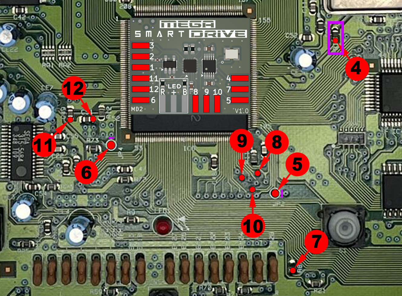
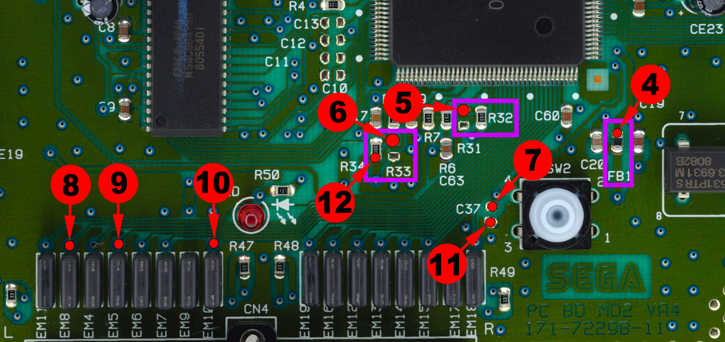
• Remove the components R32, R33 and FB1 indicated on the diagram.
• Preferably use Kynar 30AWG and flux.
• Fix the SmartDrive MD2 with quality double-sided adhesive before wiring.
To avoid stress on a fragile point:
1. First solder the wire to the SmartDrive board.
2. Then solder the other end to the previously tinned trace.
These points require lightly scraping away the protective lacquer to expose the copper.
- Then tin the solder point with a small amount of solder.
- Using flux is strongly recommended to obtain a clean and reliable solder joint.

🎮 4 - How Delta SmartDrive works
Une fois le Delta SmartDrive installed, your Sega Mega Drive / Genesis console becomes capable of easily handling regions PAL / USA / JAP ainsi que les frequencys 50Hz / 60Hz. Le changement de mode peut s’effectuer soit via la controller Player 1, soit via le bouton RESET de la console.
4.1 - Changement de region (PAL / USA / JAP) et de frequency (50Hz / 60Hz) via la controller
2. Using the controller Player 1, maintenez A + B + C + START pendant environ 3 secondes.
3. Une color bar appears on screen as an overlay, along with the color of the LED if it is installed.
4. The colors cycle according to the active mode:
6. Each time the console starts, the regional color bar briefly indicates the currently active mode.

4.2 - Selecting PAL / USA / JAP regions and 50Hz / 60Hz frequencies using the RESET button
2. Hold le bouton RESET de la console pendant environ 3 secondes.
3. Une color bar appears on screen as an overlay, along with the color of the LED if it is installed.
4. The colors then change according to the selected mode:
6. At each restart, the color bar briefly reminds you of the active region mode.

4.3 - In-Game Reset (IGR)
2. Pendant le jeu, utilisez la controller Player 1.
3. Hold la combinaison DOWN + A + B + C + START pendant environ 3 secondes.
4. La console automatically reboots.

❓ FAQ – Frequently Asked Questions
Yes, this is perfectly normal. An additional modification of the cable / adapter is required to restore correct display.
When you use a modified PAL FRA RGB adapter on an NTSC console (JPN or USA), the video signal is not fully compatible. Even after the classic modification (trace cut + PAL sync bypass), a conflict may remain that prevents correct display of the color bar.
To correct this behavior, it is necessary to:
- Keep the existing modification (PAL sync bypass)
- Add an additional trace cut on the adapter
- Precisely follow the point indicated on the diagram below